MLX90614 Voltage Compensation
Disclosure: Some of the links below are affiliate links and we only earn a small commission if you purchase through our links at no additional cost to you. The earning mainly used for maintaining the website.
The MLX90614 measures temperature without having contact with objects. So cool, right? Using a battery to power up to make it a portable contactless temperature device is even cool. Unfortunately, there is a catch when the battery is going low – voltage dropped, temperature readings may have errors.
Bad luck never lasts. The temperature errors issue can be solved easily. A minor tweak on the program to compensate for the voltage dropped saves your day. Stay till the end of this tutorial.
Temperature Errors in MLX90614
In the MLX90614 datasheet by Melexis (page 37), this sensor is calibrated at 3V. Any voltage lower or higher than 3V, the temperature errors might introduce into the readings.

Starter Pack
- Arduino Uno/Mega/Nano
- MLX90614
- Breadboard
- Jumper Wires
- Potentiometer
- Multimeter
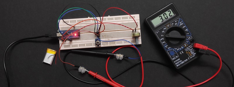
Simulate Voltage Dropped With Potentiometer
The wiring is similar to the previous tutorial. Just add a potentiometer right before Vin of the module and voltage input to the Arduino.

| Vin | 3.3V from Arduino |
| Vin | A0 |
| GND | Ground |
| SCL | SCL/A5 |
| SDA | SDA/A4 |
A wire from Vin from the module to Arduino Pin A0 functions to read voltage supply to the module.
The potentiometer is a variable resistor to reduce voltage supply. This scenario is the same as the voltage dropped in a battery when it is going low.

Arduino Program
#include <Wire.h>
#include <Adafruit_MLX90614.h>

Adafruit_MLX90614 mlx = Adafruit_MLX90614();

float voltComp;
float readAmb, readObj;
float ambTempComp, objTempComp;

void setup() {
  Serial.begin(9600);
  mlx.begin();
}

void loop() {
  voltComp = analogRead(A0) * (3.3 / 775);
  readAmb = mlx.readAmbientTempC();
  readObj = mlx.readObjectTempC();
  ambTempComp = readAmb − (voltComp − 3) * 0.6;
  objTempComp = readObj − (voltComp − 3) * 0.6;
  Serial.print(voltComp);
  Serial.print("\t");
  Serial.print(readAmb);
  Serial.print("\t");
  Serial.print(ambTempComp);
  Serial.print("\t");
  Serial.print(readObj);
  Serial.print("\t");
  Serial.println(objTempComp);
  delay(250);
}
Declare Variables
Because the readings involve decimal places, “float” variables are used here.
To store voltage supply read by Arduino.
To store ambient and object temperature.
To store compensated ambient and object temperature.
Read Voltage Supply
Arduino cannot read voltage values. Instead, it reads analog values from 0 to 1023. So, the analog values from “analogRead()” have to convert to readings we can understand.
Values from 0 to 5.0V have the division range from 0 to 1023. For reading non-5.0V voltage readings, the targeted voltage has to be divided by 5.0V and then multiple 1023.

“675” value shows a big difference from the multimeter reading. Try and error to adjust the value until the voltage reading by Arduino is almost close to the multimeter reading.

At last, “775” value is the best suit for me. The readings by Arduino and multimeter are closed to each other.

Voltage Compensation Equation
The tweak to minimize the temperature errors is to apply the voltage compensation equation. You can find the equation at the MLX90614 datasheet by Melexis (page 37). That simple only.
You may notice I stored the ambient and object temperature in “readAmb” and “readObj” rather than using the object function. I want the temperature readings to be the same for uncompensated and compensated at that point of time. So in this way, I can show that the equation can minimize the temperature errors.

Results Explanation
The readings were taken at 2.5V for low battery level, 3.0V for reference temperature, and 3.4V for high battery level. By increasing the potentiometer resistance, the voltage dropped to around 2.5V. This reflects when a battery is going low. By decreasing the potentiometer resistance, the voltage is almost maximum which simulates the battery at full level.
I do not have a controlled temperature, with a cap cover the sensor to create the so-called “controlled temperature”. This model has 900 field of view (FOV) which is quite large. Any changes in temperature in the field will be read by the sensor. So, with the cap, the area to be read by the sensor is the same. This may explain why there is a sudden high temperature reading when without the cap at 2.5V.

As seen at 3.0V, the readings for uncompensated and compensated are almost closed to each other. Meaning at 3.0V, the MLX90614 does show the smallest temperature errors. Because of this reason, I used temperature readings at 3.0V as a reference temperature.

With the voltage compensation equation applied, the temperature readings are more consistent for low and high battery level. As 3.0V is the reference temperature, so the readings at 2.5V and 3.4V minus the 3.0V to get the difference. For both compensated ambient and object temperature, the temperature readings are quite close to 3.0V. Unlike uncompensated temperature readings, the values are not consistent.
Nay! We Love Videos
Bye Bye
If you plan to use a battery to power up the MLX90614, remember to use this voltage compensation equation on your program. And also, always use a multimeter to measure the voltage supply. Make sure the voltage supply ready by Arduino is almost closed to multimeter readings by try and error adjust the value.
Hope you find this tutorial helpful in your projects. Subscribe to our newsletter for more tutorials.